User Tools
Sidebar
Table of Contents
Calibration with HSIO
This will outline the calibration of a FEI4B pixel readout using the HSIO-2 RCE. For setup and installation help see the installation section of:
https://atlaswww.hep.anl.gov/asc/wikidoc/doku.php?id=itk:hsio
The bold font indicates action items and regular text gives supplemental information.
Setting up Calibration GUI
To begin calibration disable wifi and enable ethernet connection with the HSIO-2 that is connected to your computer. Inside of a terminal, ssh into the HSIO-2 and setup the calibration server by executing this code:
$>arp -a #reveals IP addresses of devices connected to computer
$>ssh [email protected]._ #Use the IP address for rce0 obtained from arp. Password = root
$>source setup.sh #setup environment inside of HSIO-2
$>calibserver #now the calibration server is running and this terminal will provide diagnostic info
Make sure the steps here https://atlaswww.hep.anl.gov/asc/wikidoc/doku.php?id=itk:installing_local_linux_server_for_rce_communication have been done, running a dhcp server on your computer.
Next setup the calibration GUI in another terminal WITH superuser privileges:
$>cd ~/daq/rce #move to rce directory
$>source ./scripts/setup-gen3.sh #setup environment. ANL can use source setupGUIandROOT.sh to source setup-gen3 and thisroot.sh
$>calibGUI #start the GUI to interface with the rce
If any errors occur make sure the steps have been done here: https://atlaswww.hep.anl.gov/asc/wikidoc/doku.php?id=itk:installing_pixel_testing_software
Single Scan to Verify Everything is Working (Optional)
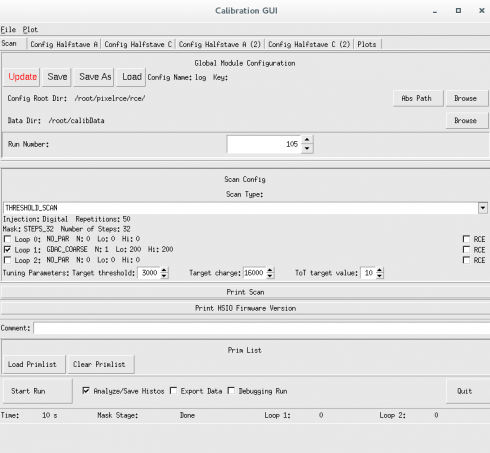
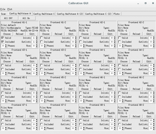
On the GUI select Save As and select a location for the log file to be saved. I simply make a directory ($>mkdir ~/daq/rce/Logs) and choose this location. The Config Root Dir should be set and then left alone once everything has been initialized (I set it to /root/pixelrce/rce). The Data Dir should be set to /root/calibData by default which is preferred. Select a Run Number which by default will automatically increment, and set a Scan Type. For this demonstration choose THRESHOLD_SCAN. On the next tab “Config HalfStave A” make sure only as many front end windows as desired are selected as “Valid” and “Included”. For this example there is only one included frontend, A1-1. Select Inlink and Outlink equal to 1 and rce equal to 0 (or whatever configuration is setup in /etc/hosts). Last and most important, select the configuration file by clicking the CHOOSE button. The default file (94-22-04_25cern6999.cfg) can be found in moduleconfigs/fei4bexample/configs/. Be sure the Address parameter (see below) is set appropriately. Returning to the “Scan” tab you may click Start Run.
The default configuration file, (94-22-04_25cern6999.cfg) is not setup for the chip geometry currently at ANL-ASC (02-06-2016). To fix this open the file and edit the 'Address' parameter from 7 to 8. Save this altered file with a new name, (ex: default.cfg).
To communicate with the rce you may need to add a line into the /etc/hosts file. Add the line: “192.168.3._ rce0” where the last digit is the one corresponding to your device (check arp -a) to this file.
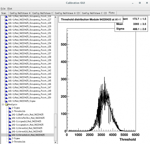
Once the test run is complete you will be able to go into the 'Plots' tab to examine the output of the scan. The results of the scan (including .root files and any calibrated configuration files) will be saved to the Data Dir (default is ~/calibData) specified before the scan is started.
If for example, I ran a FDAC_TUNE there would be a folder in the calibData directory 'FDAC_TUNE_#####'. Inside this folder there would be histograms made from the scan, and more importantly in the config/fei4bexample/configs folder there will be a new .cfg file that can be loaded in at the start of a new scan that will use the calibration already performed by the previous FDAC_TUNE. Ideally one would run these calibrations one after the other and tune different parts of the chip. The GUI has a feature that lets this be done automatically (see next section).
It useful to note that the .cfg file isn't actually what gets changed during calibration. It is merely a pointer to a series of .dat files under the fei4bexample directory substructure.
Calibrations Using Primlist
In order to fully calibrate the pixel frontend chips one simply has to run a series of calibration scans each incrementally altering configuration files until the chip becomes optimally tuned as the user desires. The Primlist feature of the calibGUI does this automatically by way of loading in a file with the desired calibration scans and their parameters.
On the GUI select Save As and select a location for the log file to be saved. I simply make a directory ($>mkdir ~/daq/rce/Logs) and choose this location. The Config Root Dir should be set and then left alone once everything has been initialized (I set it to /root/pixelrce/rce). The Data Dir should be set to /root/calibData by default which is preferred. Select 'Load Primlist' and select a text file anyName.pl that you create with the following lines:
DIGITAL_TEST,FEI4B
DIGITAL_TEST,FEI4B,CLEARMASKS=1
ANALOG_TEST,FEI4B
GDAC_COARSE_FAST_TUNE,FEI4B,THRESHOLDTARGETVALUE=3000,TOTTARGETCHARGE=16000,TOTTARGETVALUE=10
GDAC_FAST_TUNE,FEI4B,THRESHOLDTARGETVALUE=3000,TOTTARGETCHARGE=16000,TOTTARGETVALUE=10
IF_TUNE,FEI4B,THRESHOLDTARGETVALUE=3000,TOTTARGETCHARGE=16000,TOTTARGETVALUE=10
GDAC_FAST_TUNE,FEI4B,THRESHOLDTARGETVALUE=3000,TOTTARGETCHARGE=16000,TOTTARGETVALUE=10
TDAC_FAST_TUNE,FEI4B,THRESHOLDTARGETVALUE=3000,TOTTARGETCHARGE=16000,TOTTARGETVALUE=10
IF_TUNE,FEI4B,THRESHOLDTARGETVALUE=3000,TOTTARGETCHARGE=16000,TOTTARGETVALUE=10
FDAC_TUNE,FEI4B,THRESHOLDTARGETVALUE=3000,TOTTARGETCHARGE=16000,TOTTARGETVALUE=10
TDAC_FAST_TUNE,FEI4B,THRESHOLDTARGETVALUE=3000,TOTTARGETCHARGE=16000,TOTTARGETVALUE=10
FDAC_TUNE,FEI4B,THRESHOLDTARGETVALUE=3000,TOTTARGETCHARGE=16000,TOTTARGETVALUE=10
THRESHOLD_SCAN,FEI4B,THRESHOLDTARGETVALUE=3000,TOTTARGETCHARGE=16000,TOTTARGETVALUE=10
TOT_TEST,FEI4B,THRESHOLDTARGETVALUE=3000,TOTTARGETCHARGE=16000,TOTTARGETVALUE=10
NOISESCAN,FEI4B,TIMEOUTSECONDS=20
NOISESCAN,FEI4B,TIMEOUTSECONDS=20
NOISESCAN,FEI4B,TIMEOUTSECONDS=20
NOISESCAN,FEI4B,TIMEOUTSECONDS=20
On the 'Config Halfstave A' tab be sure and select 'Include' and 'Validate' for the proper ethernet connection (default = A1-1), select the proper inline,outlink, and rce numbers (default = 1,1,0 in order), and choose the starting configuration file (default is in /moduleconfigs/fei4bexample/configs , be sure to change Address 7 → Address 8). Return to the 'Scan' tab and click start scan. The scans and tunings will be ran in order, with the parameters specified in the .pl file, and the outputs will be written to the calibData directory with the new calibrated .cfg files.
To run further tests you may simply 'Choose' these new configuration files (in the previous case it would be helpful to choose the .cfg from the last noise scan) to run scans on the chip with the newly tuned configurations.
Sometimes unexpected crashes of the calibserver on the rce can occur. Simply restart this server and try again.
The logic behind the primlist file is fairly obvious and can be manipulated and altered as the user desires different parameters, orderings, or scans.
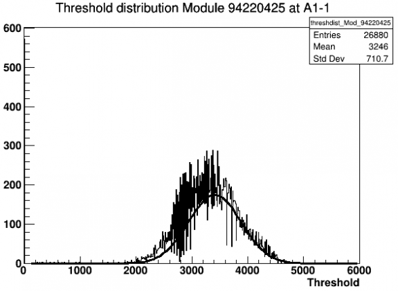
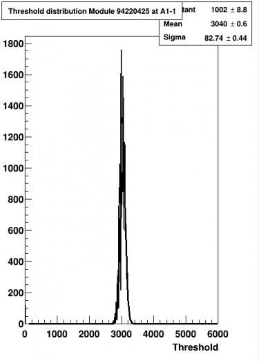
It is most instructive to run a diagnostic scan such as the THRESHOLD_SCAN on the default .cfg file, then again on the last .cfg file after the primlist has run (for example in the ~/calibData/NOISESCAN_####/config/fei4bexample/configs/ directory where #### is the last scan number). Use ROOT to compare the histograms in the two THRESHOLD_SCANs before and after to ensure everything was executed as expected. See below for example.

