User Tools
Sidebar
Table of Contents
ITK module testing
This wiki describes UsbPix teststand. Alternatively, consider using RCE, HSIO setup (see a collection of links in this page.
Setup documentation
How to test a USB3 of MMC3 card without FE-I4B To established correctly USB3 communication with MMC3, use the first 3 lines of the example usage here https://silab-redmine.physik.uni-bonn.de/projects/pysilibusb/wiki. Afterwards, you can configure the FPGA, connect FE-I4B and run a digital scan.
Windows 7 instruction
Step-by-step setup instruction for a fresh Windows 7 (64-bit at ANL)
Necessary software
- Download 7z from http://www.7-zip.org/
- Download Miniconda Python (Python 2.7, 64-bit *ANL) from http://conda.pydata.org/miniconda.html.
- Download C++ Compiler (Microsoft Visual C++ Compiler for Python 2.7) from https://www.microsoft.com/en-us/download/details.aspx?id=44266
- Download Notepad++ (optional) from https://notepad-plus-plus.org/download/v6.8.8.html
- Download Java Runtime Environment 8 (32 bits, to be consistent with Eclipse) from http://www.oracle.com/technetwork/java/javase/downloads/jre8-downloads-2133155.html
- Download Eclipse with PyDev (32-bit Eclipse IDE for C/C++ Developers) from http://www.eclipse.org/downloads/packages/eclipse-ide-cc-developers/mars1
- Download git https://git-scm.com/download/win
- Download vivoda Lab Edition from http://www.xilinx.com/support/download.html (registration needed)
- Download unzip from http://gnuwin32.sourceforge.net/packages/unzip.htm, place under pyBAR/test
- Download Make from https://sourceforge.net/projects/gnuwin32/?source=typ_redirect. Copy the make.exe from the installed directory to pyBAR/test
Install usb3.0
Follow the steps in https://github.com/SiLab-Bonn/pySiLibUSB/wiki to install the usb3.0 in windows 7
- make sure no driver installed for the cypress usb3.0 (on pixel1 computer). For “pixel2” computer, we use “renesanse” external PCI-I card.
- in Device manager looking in the “other device”→“FX3”(the one appeared when mmc3 board is connected)
- install the cypress kit from http://www.cypress.com/documentation/software-and-drivers/ez-usb-fx3-software-development-kit?source=search&cat=software_tools. Note that renaissance PCI-E USB3 card will be normally recognized by Windows 10 using some internal driver from “system32” directory. You should update it with Cypress driver (“cyusb”). Then start Cypus control center and check “Program→FX3”.
- If you use Windows 10, use these dedicated drives http://www.cypress.com/knowledge-base-article/drivers-ez-usb-fx1-and-fx2lp-kba94413?source=search&keywords=94413
- right click on the “FX3”, FX3→update diver→browse my computer of local software→C:\Program Files (x86)\Cypress\EZ-USB FX3 SDK\1.3\driver\bin\win7\x64
- Ordered List Itemopen the control center, the “Cypress FX3 USB BootLoader Device” will appear
- Ordered List Itemupload the .img file “SILABFX3” for the USB3.0 in C:\ITK\backup using control center. Select the “cypress FX3 USB BootLoader Device”→Program→FX3→RAM. Fot pixel2 computer (Windows10), use the directory “PyBarSetup” on desktop.
- use Zadig to reinstall FX3 device
- the USB devices “FX3” should show up in the Device manager
- select “FX3” in Zadig, the USB ID should be 5312 0300
- install driver WinUSB(v6.1.7600.16385)
- download libusb 1.0.20 from http://sourceforge.net/projects/libusb/files/libusb-1.0/libusb-1.0.20/libusb-1.0.20.7z/download
- Copy libusb-1.0.dll (32-bit: \MS32\dll\, 64-bit: \MS64\dll\) into your C:\Windows\System32 directory.

Install basil
Second follow the steps in https://github.com/SiLab-Bonn/pyBAR/wiki/Step-by-step-Installation-Guide
Install basil mio3
change “basil” in line 74 to “basil_daq”. You will need the branch “mio3” from github. Download the file “basil-mio3.zip”, go to “host” directory and install as “python setup.py install”. It will be copied somewhere in Miniconda directory. If you will use wrong basil, when running “python scan_analog.py”, you will get a complain about “FPGA” and “basil”.
Download pySiLibUSB from https://github.com/SiLab-Bonn/pySiLibUSB. Then replace the python file “siusbdevice.py” in pySiLibUSB/SiLibUSB/siusbdevice.py provided by the SiLab and install it as “python setup.py install.
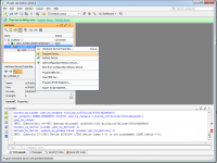
Then test the usb3 using a Python script with the following lines (The USB3 cable should be connected to the board):
import SiLibUSB
sidev = SiLibUSB.SiUSBDevice()
print "FWVersion: ", sidev.GetFWVersion()
sidev.WriteExternal(0x0000, [0xaa,0x55,0xaa,0x55])
print sidev.ReadExternal(0x0000, 4)
If succeed you should see:

If python though Error eg: “No device Found”
uninstall the driver for “FX3” in Device manager (click Delete the driver software for this device) Do search for device, then using Zadig to install the winusb dirver for it.
Program the FPGA
Need to be done every time if the board been powered off
- open vivado lab edition (or impact) *steps for vivado only
- open hardware manager
- Click on the “open taget” → “Auto connect”
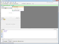
- select the connected FPGA → right click→ “program Device”
- choose the bit stream file C:/Users/pixel/git/pyBAR/firmware/mmc3/vivado/mmc3.runs/impl_1/KX7_IF_Test_Top.bit
- press “program”
- Once programmed the LEDs on the FPGA card and mother board will on. They are orange.


Data analysis
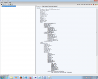
by default the raw data are converted and stored inform of HDF5 file. The .h5 file can be opened using:
vitables 56_module_test_digital_scan_fe1.h5
Data structure
Raw data
The raw data contains all FE words + FPGA trigger words + FPGA TDC words in an one dimensional array. Every word is a 32-bit unsigned int. The format is: 82444303 = 0 000 0100 1110 1010 0000 0000 0000 1111

If the first bold bit is 1 the word is a trigger word followed by a trigger number. If it is 0 the following bits indicate the FE number. This number is usually 5 when you use the single chip adapter card. With other adapter cards (e.g. burn-in card) this number identifies the different FE connected to it. The remaining 24-bits hold the FE word. For more information (e.g. TDC word) please look https://github.com/SiLab-Bonn/pyBAR/blob/master/pybar/analysis/RawDataConverter/defines.h.
Meta data
The meta data stores read out related infos:One row is added for every read out. It contains the word index at the first / last+1 word of the read out and the total numbers of words. To allow time based analysis it also has a timestamp and an error code indicating read out errors (like out of sync). The error code is not used so far.

Configuration data
All configuration parameters needed to be able to repeat the scan are stored here in different nodes. This includes the Front-End configration, the specific run configuration etc.
Parameter Data
In the parameter table the parameters that are changed during a scan is monitored (e.g. PlsrDAC setting during a threshold scan). At every readout the acutal parameter settings is added to the table. One column is reserved for one parameter.
Interpreted Data File
The raw data is interpreted, analysed and plotted with the raw data converter class. The output HDF5 file can hold hit data, cluster data, meta data and histograms at different HDF5 notes.
Hit data
The hit data table stores the information for every hit.

The columns are:
- Unordered List Itemevent_number: The absolute event number. Only events with hits appear here.
- trigger_number: The TLU trigger number. If no TLU is used the trigger number is always 0.
- relative_BCID: The relative BCID is the number of data headers of one event when the hit occured.
- LVL1ID: The LVL1ID is the internal LVL1 trigger counter value of the FE.
- column: the column position of the hit
- row: the row position of the hit
- tot: the tot code of the hit
- BCID: the absolute BCID value
- TDC: the TDC value. If TDC was not used this values is always 0.
- TDC_time_stamp: the TDC time stamp value. If not used it is always 255.
- trigger_status: the trigger status of the event where the hit occured. The trigger status error code is a sum of the different binary coded trigger error codes that occured during the event. Please take a look at the histogram section for the error code explanation.
- service_record: the service records that occured in the event of the hit. The service record code is a sum of the different binary coded service records that occured during the event.
- event_status: the status of the event of the hit. The event error code is a sum of the different binary coded event error codes that occured during the event. Please take a look at the histogram section for the error code explanation.
Clustered Data
Clustered data is usually stored as additional nodes in the analyzed data file or in a new file. The nodes are cluster hits, cluster or histograms.
Cluster hits

The table ClusterHits is a copy of the Hits table (see above) but with four additional columns:
- cluster_id: The cluster ID of the hit [0:number of cluster in the event]
- is_seed: Is one if the hit is the seed hit, otherwise 0.
- cluster_size: The size of the cluster the hit belongs to.
- n_cluster: The number of cluster of the event the hit belongs to.
Cluster
The table Cluster stores the infos for each cluster.

The columns are:
- event_number: The absolute event number. Only events with cluster appear here.
- id: The cluster ID of the cluster [0:number of cluster in the event].
- size: The number of hits that belong to the cluster.
- tot: The tot sum of all hits.
- charge: The charge sum of all hits (not used yet).
- seed_column: The column of the seed pixel.
- seed_row: The row of the seed pixel.
- event_status: The status of the event of the cluster. The event error code is a sum of the different binary coded event error codes that occured during the event. Please take a look at the histogram section for the error code explanation.
Simple data convertion
pyBAR provide few scripts under pybar/scan for raw data analysis.
python analyze_example_conversion.py (on windows 7)
(Remember to change the file name in the script to the raw HDF5 file you would like to analysis)
The converted raw data then stored as interpreted HDF5 file. It can be converted to root file using:
python convert_table_root_tree.py (on ATLAS cluster)
(Remember to change the file name in the script to the interpreted HDF5 file you would like to convert)
After computer shutdown
FX3 and FPGA firmware that you are uploading is not permanently stored on the board. Instruction from Viacheslav Filimonov:
Data analysis
— Sergei Chekanov 2016/01/02 03:17 — Rui Wang 2016/03/02 02:27
