User Tools
Sidebar
This is an old revision of the document!
Table of Contents
Pixel module test beam
(prepared by S.Chekanov)
Here are the useful links on test beam in Sep. 2016 at SLAC. The plan is discuses on this wiki at SLAC.
What is used: 11 GeV secondary electrons (~100 - 200 per bunch), 5 HZ frequency. Original electron beam is 14 GeV. The setup is described in Setup at SLAC. To start the run, use:
  ssh -Y esadutdaq1 -l tbslac
  cd ~/daq/rce
  source ./scripts/setup-gen3.sh
Details on 2 tests:
1) Testing RTI (USA vendor) to test bum bonding. We use 2 V for low voltage and max 0.5 A. We set -80 V as bias voltage for RTI (FE-I4B) board.
2) Testing RD53 FE65-P2 prototype (radiation damage). Features:
- 50x50um pixel size (vs 50×250 um for FE-4IB)
- Readout ASIC with 65 nm (vs 130 nm for FE-4IB). This decrease of ASIC leads to smaller sizes.
How to make calibration
This description is valid for the second (green) readout module installed on Sep 29, 2018. with RTI chip/sensor. Low voltage was 2 V (0.3A current), with the shift voltage of -86 volts. The first module installed on Sep 28 had some problem (high noise of 500e), and later start to show problem for the analog part (30 counts vs expected 50, and no data for the threshold scan).
Start “calibserver” on RCE computer located on HSIO board. Sometime you will need to reboot it, so “calibserver” starts after reboot automatically. If not, ssh to rce computer (as root) and check “ps -aux | grep calibserver”. If it is not running, reboot the rce computer (calibserver starts automatically).
Then start “calibGui” on the main computer (tbslac@esadutdaq1). First, start from a configuration file which does not point to any mask/tune files.
/home/tbsclac/pixelrce/rce/moduleconfigs/RTISC2B/configs/RTISC2B__cern__6999.cfg
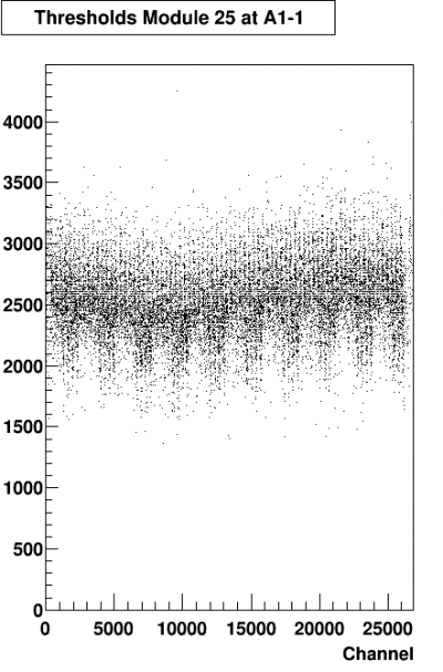
(note the name of this file - it was originally prepared for the red board, but we are reusing it for the green too). This file does not point to any calibration files, so use it for a check. Make “ANALOG” and “DIGIT” scans, and then “THRESHOLD_SCAN”. Typically, your target is 3000 e, total change 16000 at TOT value 10. But you will not see that this is not exactly true for the un-calibrated chip - it will show the threshold value at around 2500e, with a very large RMS (300).
Now, you calibrate the chip. You can preload a list of test as shown below:
DIGITAL_TEST,FEI4B
DIGITAL_TEST,FEI4B,CLEARMASKS=1
ANALOG_TEST,FEI4B
GDAC_COARSE_FAST_TUNE,FEI4B,THRESHOLDTARGETVALUE=3000,TOTTARGETCHARGE=16000,TOTTARGETVALUE=10
GDAC_FAST_TUNE,FEI4B,THRESHOLDTARGETVALUE=3000,TOTTARGETCHARGE=16000,TOTTARGETVALUE=10
IF_TUNE,FEI4B,THRESHOLDTARGETVALUE=3000,TOTTARGETCHARGE=16000,TOTTARGETVALUE=10
GDAC_FAST_TUNE,FEI4B,THRESHOLDTARGETVALUE=3000,TOTTARGETCHARGE=16000,TOTTARGETVALUE=10
TDAC_FAST_TUNE,FEI4B,THRESHOLDTARGETVALUE=3000,TOTTARGETCHARGE=16000,TOTTARGETVALUE=10
IF_TUNE,FEI4B,THRESHOLDTARGETVALUE=3000,TOTTARGETCHARGE=16000,TOTTARGETVALUE=10
FDAC_TUNE,FEI4B,THRESHOLDTARGETVALUE=3000,TOTTARGETCHARGE=16000,TOTTARGETVALUE=10
TDAC_FAST_TUNE,FEI4B,THRESHOLDTARGETVALUE=3000,TOTTARGETCHARGE=16000,TOTTARGETVALUE=10
FDAC_TUNE,FEI4B,THRESHOLDTARGETVALUE=3000,TOTTARGETCHARGE=16000,TOTTARGETVALUE=10
THRESHOLD_SCAN,FEI4B,THRESHOLDTARGETVALUE=3000,TOTTARGETCHARGE=16000,TOTTARGETVALUE=10
TOT_TEST,FEI4B,THRESHOLDTARGETVALUE=3000,TOTTARGETCHARGE=16000,TOTTARGETVALUE=10
NOISESCAN,FEI4B,TIMEOUTSECONDS=20
NOISESCAN,FEI4B,TIMEOUTSECONDS=20
NOISESCAN,FEI4B,TIMEOUTSECONDS=20
NOISESCAN,FEI4B,TIMEOUTSECONDS=20
This file should be saved to “2016_sep28_3000e.pl”, and loaded to “primelist”. Note: last 4 tests crashes calibserver, so you need to reboot “rce” every time. Martin was informed about this error. You do not to make this file, since it is already in
/home/tbsclac/pixelrce/rce/moduleconfigs/RTISC2B/2016_sep28_3000e.pl
(it does not contain 4 noise scans).
Load this file using “Load Primelist” button and press “Start Run”. When you finish all 14 calibration tests (takes 3 min), the last number in the GUI shows which configuration file contains calibration (actually, this number minus 1).
For example, after finishing the calibration, the last created calibration file is
/home/tbsclac/pixelrce/rce/moduleconfigs/RTISC2B/config/RTISC2B__cern__158.cfg
This files points to some files with the calibration data. You should load this file. Normally, this configuration file is inserted to the calibGui automatically. If not, go to the tab “Config Halfsatve A”, click “Choose config” and load this file. “Inlink, Outlink, Rce” should be 0. “Phase=0”. There will be 2 tick marks “Valid” and “Included”.
Now, check the quality of the calibration. First, remove primelist by pressing “Clear Primelist” button. Then go to “Scan” tab and run “THRESHOLD_SCAN”. Then check the histograms.
Here are examples of the plots for the calibration taken on Sep 29, 2016, 6pm, after access. At that time, the calibration file was:
/home/tbsclac/pixelrce/rce/moduleconfigs/RTISC2B/config/RTISC2B__cern__93.cfg
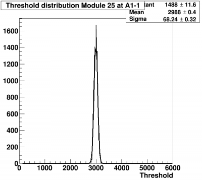
You will see the correctly filled histograms. The most important is this:
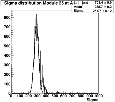
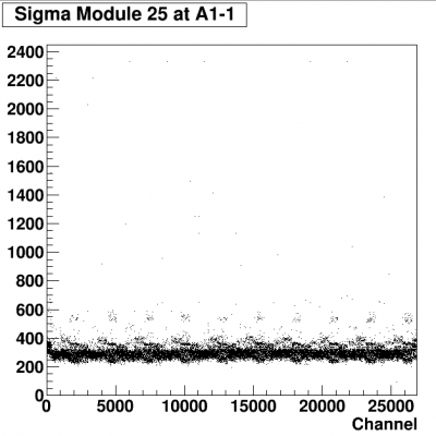
which show small RMS and a peak at 3000 (since we required this in the GUI). Here are other important plots:
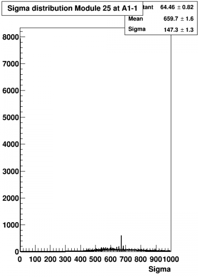
Look also at the noise:
And bad pixels:
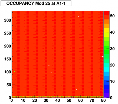
Here is digital scan plot for each channel (usually looks very good, with 50 counts for every channel)
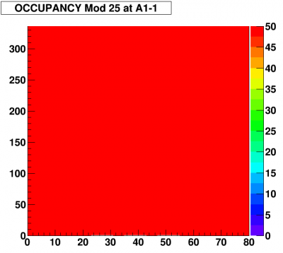
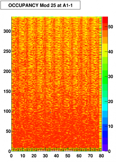
The occupancy for the analog scan shows some features, and a few low-occupancy channels:
September 30, 2016
The plots you see above were done with the calibration done on Sep 29, 2016. The calibration taken on Sep. 30 shows some changes.
Here are the plots without any calibration from Sep 30:
It is clear that analog channels become inefficient during the time since Sep 29 when this module was installed.

