Table of Contents
FLIC-FTK Level-2 Interface Card
The Fast TracKer (FTK) to Level-2 Interface Card (FLIC) of the ATLAS FTK trigger upgrade is the final component in the FTK chain of custom electronics to connect the system to the High-Level trigger (HLT). The FTK performs full event tracking using the ATLAS Silicon detectors for every Level-1(L1) accepted event at 100 kHz. The FLIC is a custom Advanced Telecommunications Architecture (ATCA) card that interfaces the upstream FTK system with the ATLAS trigger and data acquisition (TDAQ) system, and allows for event processing on commercial PC blades, making use of the 10 Gb Ethernet full mesh ATCA backplane.
FLIC specification 04022016_atlas_ftk_creat_sys_spec_1.7.2.pdf
FLIC register map current_flic_register_maps.pdf
FLIC user manual flic_user.pdf
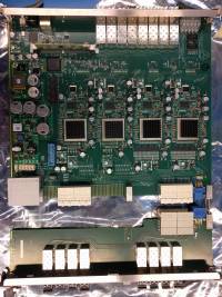
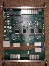
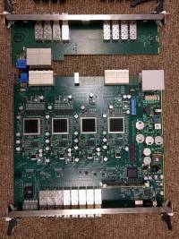
FLIC production boards
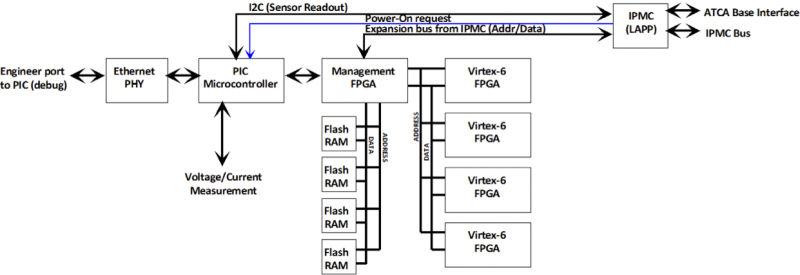
FLIC hardware design
- 18-layer circuit board, standard FR-4
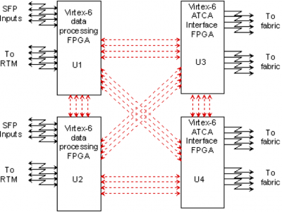
- 2 Virtex-6 FPGAs as the data processor (1&2)
- Each has 128 Mbit of fast SRAM (32 Mbit per SFP input) to implement data-driven lookup tables
- Track geometry data from the lookup table are inserted into the data stream “on the fly”
- 2 Virtex-6 FPGAs as the ATCA interface (3&4)
- Each implements two 10Gb Ethernet interfaces to ATCA backplane (total 40Gb output bandwidth)
- Each has 8 SERDES links of input from I/O processor FPGAs, matched to total ATCA output bandwidth
- Distribute data, from the FLIC to the multiple processor blades
- Full, matched-bandwidth internal mesh of SERDES links between all FPGAs
- General-purpose DDR3 memory per FPGA forbuffering or event record building
FLIC slow control
FLIC Data format
The new data format agreed on March 7th,2016 is summarized in 20160402_flic_data_formats_checking.xls
SSB to FLIC input data format
FLIC to HLT output data format
SSBe
Spy buffer
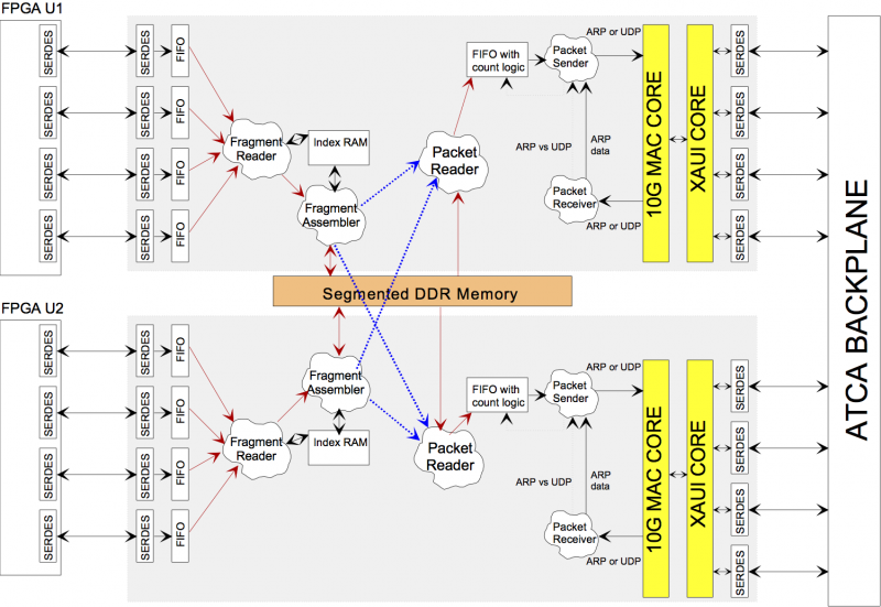
The FLIC spy buffer copy the tagged events from U1&U2 to U3&U4 then assembly them into ethernet package and send to ATCA processor blade via 40Gbps ATCA back plane. u3_u4_design_overview.pdf 20150629_spy_buffer_spec.pdf
Processor Blade
The manual for the adlink processor blade 6150 at ANL441142.pdf.
The manual for the adlink processor blade 6155 at CERNatca-6155_50-1g019-1000_200_en.pdf
ATCA shelf
IPMB address for the slots
| Slot | IPMB address |
| 1 | 82 |
| 2 | 84 |
| 3 | 86 |
| 4 | 88 |
| 5 | 8a |
| 6 | 8c |
Shelf Manager
Power control
To turn on and off boards, follow the procedure in this link: https://docs.google.com/document/d/1AFG2NiOa7EOsIhMX3Na6mmfUw2Ab1HVlt_Txr5kHMYE/edit?usp=sharing
IPMC
Talk to the IPMC.
eg. get the device ID of the board in slot 3:
clia sendcmd (IPMB address) (netfn) (command)
clia sendcmd 86             6       1
get Device SDR Info:
clia sendcmd (IPMB address) (netfn) (command)
clia sendcmd 86             4       20
More detailed IPMI command can be found here: https://docs.oracle.com/cd/E19175-01/820-3148-10/Firmware.html#50487327_17788

